44A, Dokki St., Misr Insurance Rear Tower, Floor 12 – Flat 125, Giza, Egypt

Types
Hydrographic / Topographic / Cadastral / GPS / GIS
Services
Utility and pipeline routing / Verification of line-of-sight / Construction layout / As-built / CAD modeling / Monitoring
Operations
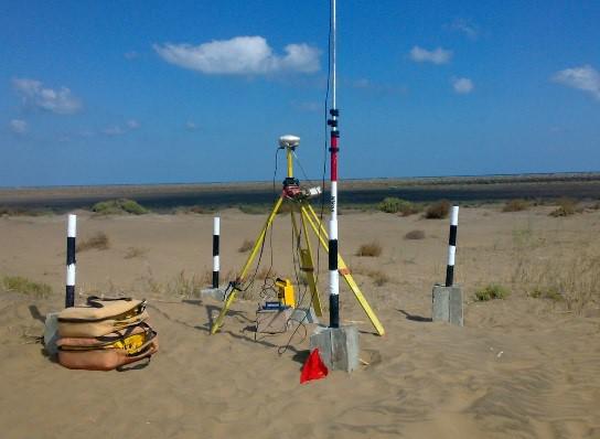
- We establish horizontal and vertical control networks, with the number of stations dependent on site conditions, using permanent concrete survey monuments. For certain projects, the control points are tied to the National Geodetic Network and Benchmarks.
- For other projects, control points are determined locally, and are dependent upon customer requirements. To reach the maximum achievable accuracy, the horizontal coordinates and elevations are computed and adjusted with powerful computer software.
- For full site cadastral mapping, we survey all surface and detectable sub-surface features within the site, including buildings, roads, power lines, water pipelines, wastewater pipelines, gas pipelines, canals and drains, green areas, and trees.
- We perform grid leveling with sufficient intervals, depending on site conditions and client needs, and produce comprehensive contour maps. Grid leveling and contour map drawings are generated in 2D or 3D format, according to client needs.
- Spot elevations that affect the construction of facilities, such as break points, tops of hills, bottoms of ditches and gullies, are typically carried out and then plotted on contour maps.
- Volume computations, including a determination of volumes of cut and fill, are compiled with computer software using advanced methodology.
- We set out axes markers, property boundaries, and special markers in accordance with project specifications and our client's requirements.
- Longitudinal leveling (profiles) is at designated intervals along the alignment of the centerline of roads, power lines, and water, wastewater, and gas pipelines.
- We carry out cross-sectional profiles at designated intervals and perpendicular to the alignment of the centerline of roads, power lines, and water, wastewater, and gas pipelines, as well as cross-sectional profiles for canals and drains.
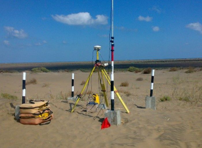
- We use GPS to determine the coordinates of control points in static and semi-kinematics modes and kinematics applications, including positioning, velocity, acceleration and alttitude determination for advanced applications with Geographic Information Systems for long-route coordinate positioning.
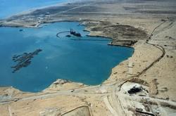
- Hydrographic surveys for areas under water are conducted using a grid election network (bathymetric survey) to determine the depth of the sea bottom, with grid intervals dependent on site conditions and client needs.
- All field data is recorded in digital format.
- All of our drawings are computer generated in 2D or 3D format using the final tape version of data and plotted in AutoCAD output format.
- We produce base maps to support GIS applications.
Equipment
Trimble
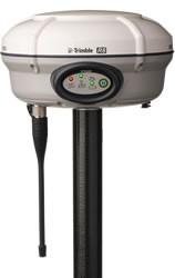
- Trimble GPS system model Trimble R8 GNSS Dual frequency, 120 channel.
- Trimble R8 GNSS GPS receiver + 3 units Satel 3AS GFU14-1 radio modems
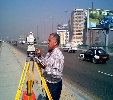
- Trimble total station 5503 + Trimble Business Center software + Radio Detection electromagnetic locators model RD 400 PDL2 with accuracy 10 cm in location and +/- 5% accuracy in depth
Sokkia
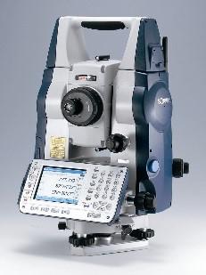
- Sokkia SET 3X, 1" (two units), non-prism technique optional and with a complete set of reflectors (single, triple, etc.) + SOKKIA electronic total station (SET 3C), with a complete set of reflectors.
- SOKKIA POWERSET electronic total station, with a complete set of reflectors.
WILD
- WILD (D14) Distomat. An Electronic Distance Measuring (EDM) device capable of measuring distances up to 1 km, which can be mounted on WILD Theodolites.
- WILD T2 Theodolite, with I" accuracy in measuring horizontal and vertical angles.
- The WILD T2 can be attached to the WILD (DI4) Distomat to provide full information on determining the 3D positions of points and for contouring purposes.
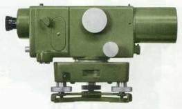
- WILD NA2 Automatic Precise Level + WILD NAKO Level + Three WILD NA2 Level + WILD N01 Level
PENTAX
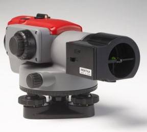
- PENTAX AFL-320
Software
GEC has developed its own software to suit different applications, and our programmers are highly capable of developing special software when needed.
SDR
- complete commercial surveying computation package
- data transfer from the total station, data processing and plotting.
- mapping, contouring, longitudinal + transverse profiling of road design and volume computations.
- output can be used in different CAD formats
SURFER
- commercial software for mapping, contouring and volume computation
